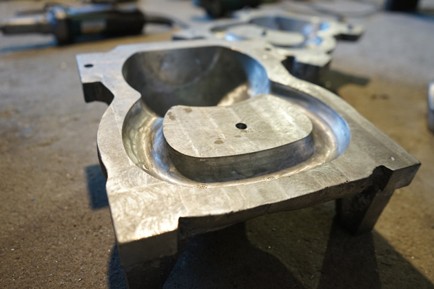
In the metalworking industry, casting pattern is a replica that has similar shape and dimension to the casting. The casting patterns are used to press into the sand mold to create the hollow cavity that allowing molten metal to be poured into and forming the casting.
In the sand casting foundry (whichever cast iron casting, aluminum casting or steel casting), a pattern set includes pattern, gating system feefer head, riser and pattern plate.
The material, design and structure of the pattern put greatly effect on the quality of products. Similarly, the running and pattern making cost can be well-awared in the casting expenses.
Casting pattern materials in the metal casting
Tips to choose patterns materials
– Sturdy and durable: choose the patterns materials that last long, not warp or change shape during casting process.
– Anti-abrasion and water resistance: it is vital to choose the materials that are water resistant and anti-corrosion to protect the casting patterns from being rust and degraded.
– Easy to form: unaffected by changes in temperature and humidity.
– Low cost and smaller weight: this ensures a balance between cost and profit for your foundry.
Choose material for pattern making
To ensure these above criteria and depend on specific industry, the pattern materials should be considered with its flexibility. Metal, wood and plastic are the priorities materilas in patternmaking process.
- Metal patterns: The patterns made by metal will ensure the hardness as well as be easy to shape. Nevertheless, the weakeness of metal patterns is that it is easy to be rust and features heavy mass. Plus metal pattern material also requires advanced devices and is difficult to repair causing higher cost in overall comparison.
There are metals commonly used in the pattern making process such as grey iron, steel, aluminum, and magnesium. Each of these pattern materials have a different shrinkage property.
- Wood patterns: is a very popular pattern material due to its avaibility and small mass. Additional, wooden can be form easily with far cheaper cost than metal patterns. However, the downside of wood pattern is easy to absorb moisture and being warped.
- Plastic patterns: Plastic and fiberglass are trends these days because their biggest advantage is light mass, waterproof and chemical resistant. Plus, the surface finish of plastic is excellent gloss. Yet, this material cons is easy to be crack while facing up with strong impaction or vibration during the casting process.
- Other materials: Wax and Paris plaster are also used as the pattern materilas for the casting process but it is only preferable in investment casting technique.
Types of casting pattern in metalworking
There are a range types of pattern in metal casting and each types suit on specific casting requirements. Here VIC sorts out the mainly 3 casting pattern types mostly seen in metal foundry.
1. Single Piece Patterns

Single piece pattern is the cheapest pattern type. This sort is often used in the case where the casting is simple, the surface is flat and production volume is small as well as in prototype development.
2. Split or Two-Piece Patterns
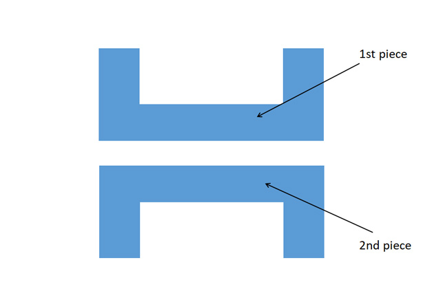
Two piece pattern is common in casting intricate objects. This pattern type is split to parting planes and the position of the plane is decided by the shape of casting.
The pattern is divided into two parts, one of the parts is molded in drag and the other one is molded in cope. The cope part always has dowel pins that matches with the precisely made holes in the drag part of the pattern.
3. Segmented or Multi Piece Patterns
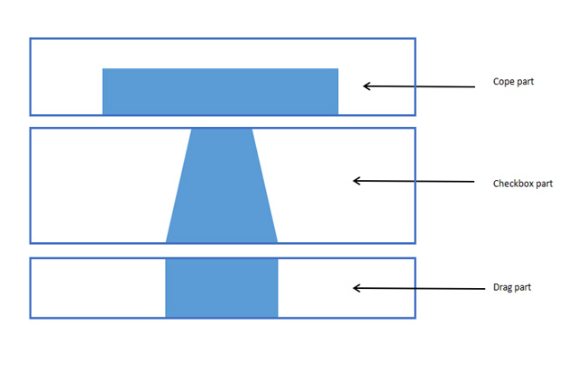
Multi piece pattern prefers to cast super complicated casting parts that are impossible to make by other pattern making methods. This pattern has three parts: top, middle and bottom part.
The top part is cope part, the bottom part is drag part and the middle one is checkbox part. It is used in various kinds of joints such as mitre joint, dowel joint.
Casting pattern making process in foundry
1. Pattern designing
The technical department working on casting patternmaking has to carefully consider the casting drawing to design pattern as tight and effective as expected.
The most important points have to take in account including parting plane, shape and dimension of the casting and core, plus pattern material.
Step 1: Decide the parting plane
Usually the parting plane is coincided with the parting mold line.
If the pattern is in spilit piece pattern type or multi piece pattern, the upper and lower parts must be clearly defined even when the dividing surface is symmetrical.
Step 2: Determine the shape and dimension of core print supportive.
Core print supportive is used to support core print to be fixed in the mold.
Tolerance of core print supportive will directly affect on dimensional tolerance inside the mold. Hence, it need to consider the core print shape, gap between the core and pattern together with pattern assemble process to design exactly core print supportive.
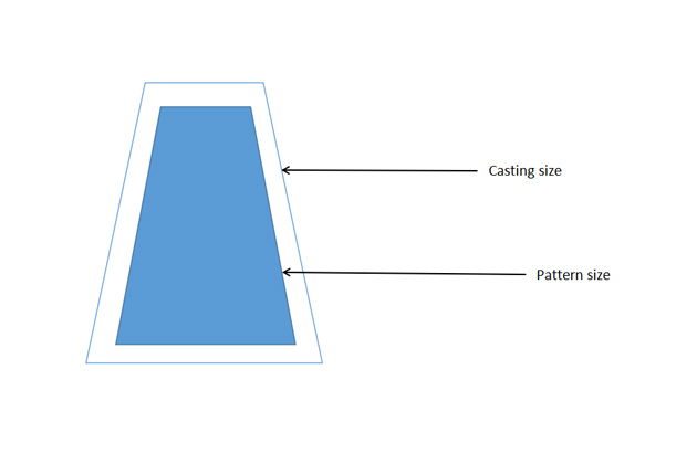
Step 3: Determine pattern dimensiona and allowance
With the pattern has parting planes, each part have a different dimension and once these parts are assembled they have to be respectively with the casting dimension.
If the pattern is made of metal, when condensed, it will shrink. Therefore, if you take the correct size of the casting drawing as a model, the size of the casting will be smaller significantly. To solve this problem, the mold cavity must be enlarged and the pattern size must be larger than the casting size by a proportion of shrinkage of the metal. This is determined based on pattern allowances.
Step 4: Determine the pattern materials
- Wooden pattern: If the pattern is small, it can be made of solid wood. If the pattern is larger and more complicated, it must be made of cut wood. To represent a wooden pattern drawing, you can draw full views and sections, or use puzzle piece symbols to save time and ease reading.
- Metal pattern: Applicable to mass production or high volume order. If the pattern volume is large, it is advisable to make pattern with internal hollow metal to reduce weight and save material costs. If the pattern is small, then choose solid metal.
Step 5: Located while assembling pattern
For circular samples with parting plane perpendicular to the centrifugal shaft, only 1 dowel pins are needed.
For other types, use 2 or 3 dowel pin.
In principle, the more distance between dowel pins, the more accurate the positioning is. The pin and hole structure must be of reasonable size for easy withdrawal and disassembly. For patterns with split planes, the dowel pins of the cope part must match the precisely made holes of the drag part.
In addition, on the pattern drawing it is necessary to specify the surface smoothness and paint color of the parts of the pattern.
2. Casting pattern allowances
Pattern allowances reflect the properties of the cast metal. When the pattern is maded, certain allowances must be given on the sizes specified in the finished component drawing so that a casting with the particular specification can be made.
There are allowances as the following:
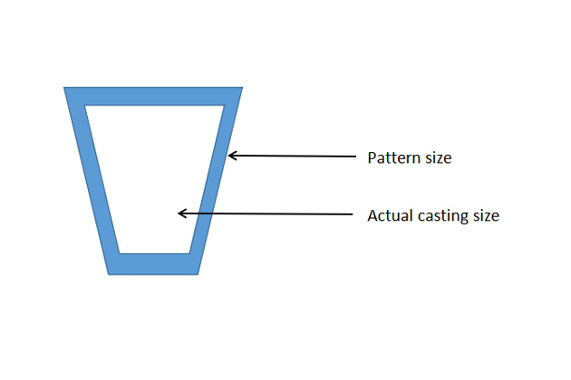
Shrinkage solidification (or contraction allowance)
Most metals have shrinkage during cooling, which is the transition from liquid to solid (called liquid shrinkage) and cooling in solid form (called linear contraction).
Shrinkage of a liquid is a decrease in volume during solidification (from liquid to solid). The liquid shrinkage is accounted for by risers, which feed the liquid metal to the casting, are provided in the mold.
Solid shrinkage is size reduction while reducing heat when metal casting is in solid state. To account for this, shrinkage allowance is provided on the patterns.
Shrinkage rate and level depend on what the material is. The following table shows shrinkage rates for different metals.
| Material | Shrinkage |
| Grey iron | 1% |
| Steel | 2% |
| Copper/Aluminum | 1.5% |
| White iron | 1.5% |
| Magnesium | 1.6% |
Note: Shrinkage also depends on the size of the material, the longer the size, the higher the shrinkage.
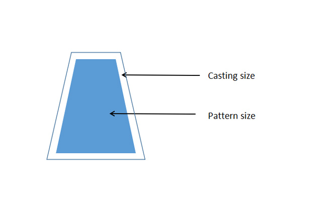
In essence, the pattern making process shrinkage formula is:
Pattern size = casting size + metal shrinkage
However, when recording on the drawing, it is still required to take data according to the casting drawing. When fabricating patterns, use size ratios depending on different cast alloys.
Draft or taper allowance
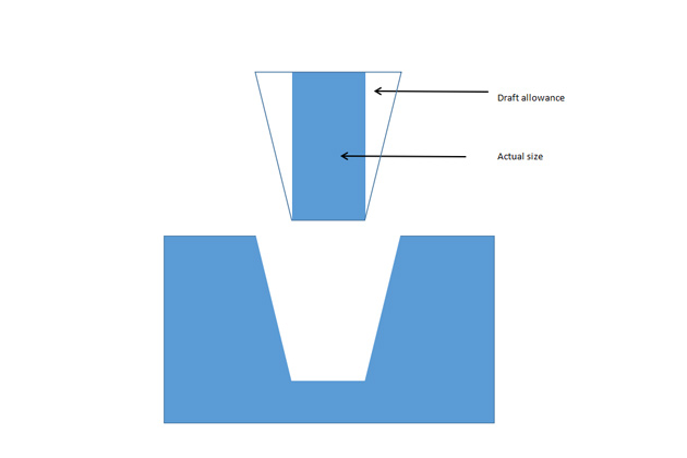
When the pattern is removed from the sand mold, the walls of the mold can be rubbed with the pattern resulting in the pattern being torn and damaged. To avoid this, taper on all vertical surfaces of the pattern must be created, this is called draft allowance.
Here, the moment the pattern lifting commences, all of its surfaces are away from the sand surface. Therefore the pattern can be removed without damaging the mold cavity.
The angle draft is created for all of faces of the pattern, which are parallel to the draw direction for facilitating the process of withdrawal. Depending on the size of the outer faces, the value of the Angle draft is in the range 0.5 – 3 degrees.
| Material | Height of the given surface (inch) | Draft angle (External surface) | Draft angle (Internal surface) |
| Wood | 1 1 – 2 2 – 4 4 – 8 8 – 32 | 3.00 1.50 1.00 0.75 0.50 | 3.00 2.50 1.50 1.00 1.00 |
| Metal, plastic | 1 1 – 2 2 – 4 4 – 8 8 – 32 | 1.50 1.00 0.75 0.50 0.50 | 3.00 2.00 1.00 1.00 0.75 |
Finishing or Machining allowance
The surface of the collected casting is usually not correct in size, so machining, such as turning or grinding, must be done to improve the surface finish quality.
Since machining removes an amount of metal from the casting, an amount of metal called a machining allowance must be offset. The machining allowance is influenced by the casting method, the size of the casting, the casting material, and the finishing posibility of the casting.
| Metal | Dimension (inch) | Allowance (inch) |
| Cast iron | Up to 12 12 to 20 20 to 40 | 0.12 0.20 0.25 |
| Cast steel | Up to 6 6 to 20 20 to 40 | 0.12 0.25 0.30 |
| Non ferrous | Up to 8 8 to 12 12 to 40 | 0.09 0.12 0.16 |
Distortion or camber allowance
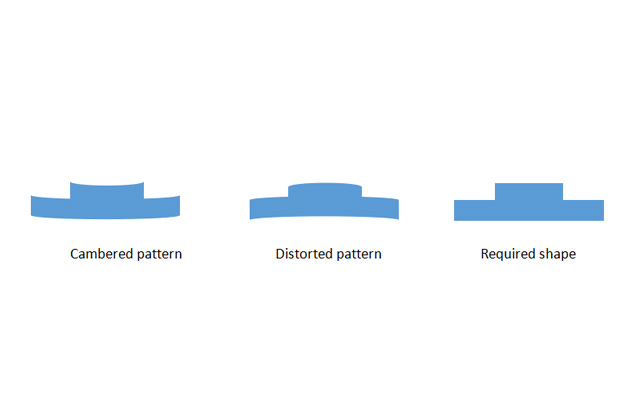
During solidification, if the casting has the shape L, U, V, T, … or is thinner than the length, it will tend to be deformed in vertical planes.
The reason causes this problem is that the internal stresses developed in solid metal. These internal stresses are caused by the uneven cooling of different parts of the casting, which causes conflicts in condensation, it is called distortion allowance or camber allowance.
The remedy for this situation is to modify the casting design in the direction of initially distorting the pattern in the opposite direction. The degree of distortion to fix is evaluated based on the experience of the pattern maker.
Rapping or Shaking Allowance
In the process of removing the pattern from the sand mold, with large patterns or high precision casting, it is required to rap around the vertical surface of the pattern to expand the mold cavity and then pick up the pattern easier. It only applied to those dimensions that are parallel to the parting plane.
To compensate for this, we need to reduce the original pattern size. There is no standard formula to calculate this allowance because it depends very much on the worker.
Core and core print
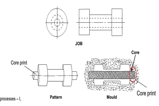
A core is used to create holes or recesses in a casting. The core is usually made of green or dry sand.
Core print is provided in the mold for locating, positioning and supporting the core. The sand core will stay at that position when the molten metal is poured into the mold.
Core must be placed horizontally, vertically or hung inside the mold cavity. However, the core cannot self-hang inside the mold cavity without any support. The core print is prepared with the help of projections on the pattern. But the problem is that while removing the pattern, the mold gets damaged due to the presence of that projections. Therefore, split pattern is used for casting process in which the core is used.
Core print must be of the appropriate size and shape to withstand the weight of the core and the buoyancy of the molten metal around it during casting.
3. Patternmaking
Design Gating system
Each pattern will include a gating system to pour liquid metal into the mold cavity. The gating system is very important because it regulates the speed at which metal is poured into the mold. If the speed is too fast it can cause mold corrosion, if too slow it can cause the metal to cool down before filling the cavity.
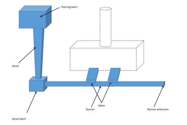
This gating system consists of the following connected parts:
- Pouring cup: is a cone shaped input into the mold. It helps to control turbulence of metal flow and stabilizes flow rate, as well as separates slag during pouring.
- Sprues: a funnel that leads molten metal from a pouring cup into the tapered sprue, then through the runner, going into the gates one after another.
- Gate: is the end of the path, this is where Mold Cavity begins.
There are two types of gates: big gate and small gate. Large gates are used to cool the metal quickly and smaller gates are used for slow cooling. Depending on the requirement on the condensing rate of the casting, a reasonable gate is used.
- Riser: Is a molten metal cavity and is part of the mold provided to compensate for metal shrinkage as it reduces temperature and helps prevent holes. Riser is where liquid metal cools slowly. Based on the riser, the worker will know whether the die is filled or not.
If the casting has holes in the design, the core must be placed in the mold to determine the position where the metal will not flow.
Sometimes it is possible to place chills on the pattern surface before casting to cool locally to determine the cooling order of liquid metals. Chills can be easily recovered and reused as they are just pieces of metal that have a much cooler temperature and do not cling to the casting.
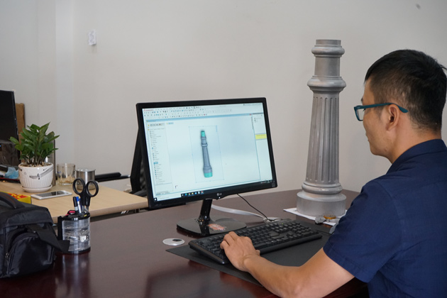
Gating systems can be designed manually or using automated softwares.
The details about designing Gating system: https://vietnamcastiron.com/gating-system/
Pattern making
As mentioned, patterns come in a variety of different materials, including wood, metal, plastic and wax. Wood and metal pattern materials are commonly used for sand casting, while wax is commonly used for investment casting.
Patterns have different complexity, depending on the size, shape and quantity required.
In investment casting, when each wax pattern is destroyed during casting, a wax pattern is needed for each casting and these wax patterns are created in the mold. Wax is filled into these molds, and after cooling, the mold is separated and the one-piece wax pattern is extracted.
For sand casting, normally the pattern is made from metal or wood pattern. If high precision is required, it will be processed by CNC machine.
Summary
Thus, VIC has answered all the questions about how to make a casting pattern in the metalworking industry and notes in the process of patternmaking.
The finish and size of the casting depend a lot on the casting pattern, and hence, determines the success of the casting product quality. Therefore, patternmaking is a profession that requires experience as well as a high level of working expertise.
Please follow the casting blog series with VIC to update more knowledge about the casting industry. Also, do not hesitate to email us if you are seeking out for an OEM / ODM manufacturer in the casting industry via: [email protected].
Hi Very informative, keep establishing actively, warm regards, Boopathi.