In sand casting, the metal pouring system is extremely crucial because its layout affects the quality of the casting and reduces metal wastage on the pouring system. In this article, VIC will give you a detailed look at the gating system in the casting process.
What is the gating system in casting?
In the metal foundry, the gating system in casting is a metal pouring system that conducts molten metal into the mold cavity. Metal flows down from the pouring basin into the sprue and passes through the runner and gates before entering the mold cavity.
Designing a gating system requires careful consideration according to the technology, materials, and castings.
This system determines the flow rate of metal to the mold cavity.
If the flow rate is too fast, there is a risk of corrosion while if the speed is too slow it can cause the metal to be cool before filling the chamber, which directly affects the quality of the casting.
The shape and size of the gating system in casting are properly arranged when making the mold. If the gating system is not designed properly, it can cause severe casting defects.
Dm me for help: https://dareplayio.blogspot.com/2022/09/dareplay.html
Functions of gating system in sand casting
The gating system in casting is designed to serve the following 4 main goals:
- Fill the mold cavity with enough metal in the shortest time without having to increase the metal temperature.
- The metal flows smoothly, minimizing turbulence that causes air trapping during casting.
- The gating system sets the appropriate temperature range so that during the metal cooling process, shrinkage will occur in the gating system, not in the casting parts.
- Combined with metal impurities removal system.
Design requirements of the gating system
A well-designed gating system in casting should satisfy the following requirements:
- Good control of metal flow. No impact, no splashes, smooth and steady continuity.
- Do not carry slag, impurities and gases into the mold cavity.
- Fills the mold cavity quickly, does not reduce the dilution of metal.
- Controlling the temperature in the mold cavity to cool the metal stably.
- Capable of adding metal and not wasting much metal.
- Easy to disassemble after the casting has solidified.
- Economic and maximizing casting yield.
If the gating system is designed incorrectly, the following errors can occur:
- Oxidizing metals.
- Corrosive to mold.
- Causing shrinkage of objects in the mold.
- Make metal penetrate the mold wall.
- Cool uneven casting.
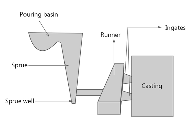
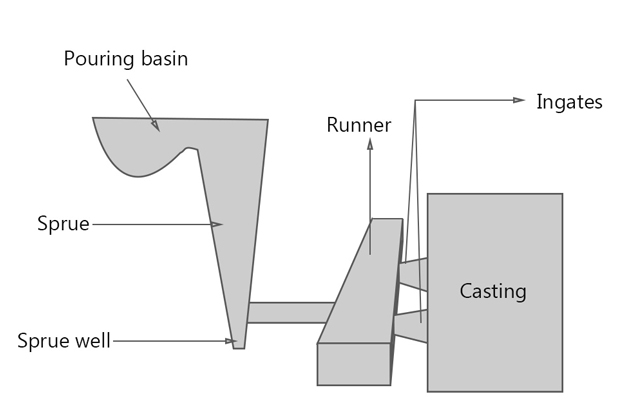
Gating system diagram
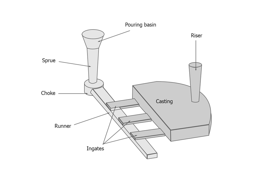
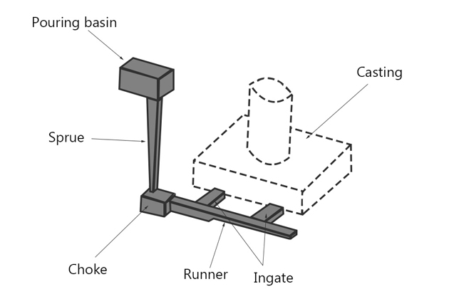
The gating system in sand casting includes:
1. Pouring basin or pouring cup
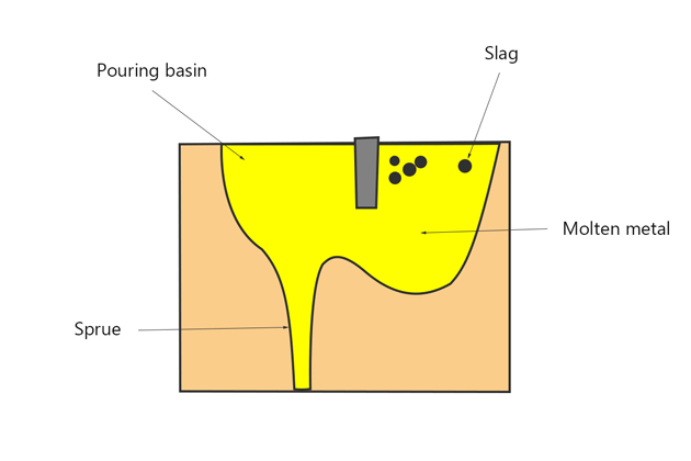
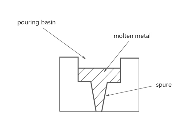
The Pouring basin is the funnel-shaped inlet, located on top of the system, where metal is poured from the ladles into the mold.
Pouring basin helps to regulate the flow rate of liquid metal and reduces turbulence at the sprue entrance, and helps to separate sediment and slag before entering the sprue.
2. Sprue
Sprue casting is a vertical passageway from pouring basin down runner and gates. Liquid metal going down the vertical sprue loses pressure but increases speed due to the effect of gravity.
The sprue cross section can be circular, square or rectangular (preferably circular). Sprue is designed to taper down to avoid air aspiration. Bigger end above for metal pick-up, while smaller end connects to runner.
The foot of the sprue is rotated at a right angle to the runner to prevent free fall of liquid metal, known as the sprue well.
3. Cross gate or runner
Runner in casting is a horizontal channel connecting the sprue well to the gates. Liquid metal will flow from the sprue to the runner and fill the mold cavity appropriately. Runner has the effect of slowing down the speed of liquid metal when it is free falling in a high speed sprue.
Runner must be filled with molten metal to prevent slag from entering the cavity and ensure steady flow.
4. Ingate (or gate)
Ingate is the end of the path and where the mold cavity begins. It leads the liquid metal that flows from the runner into the mold cavity. Depending on the characteristics of the casting, there are different number of ingates.
There are two types of gates: big gate and small gate. The small gate is used for slowing solid casting, while the large gate is for fasting solid casting.
The gate should not have sharp edges as they can crack during pouring so that the sand can be caught in the molten metal into the mold cavity.
Types of gates in casting:
Gate is divided into 3 categories:
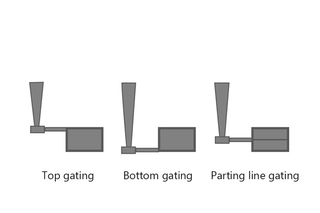
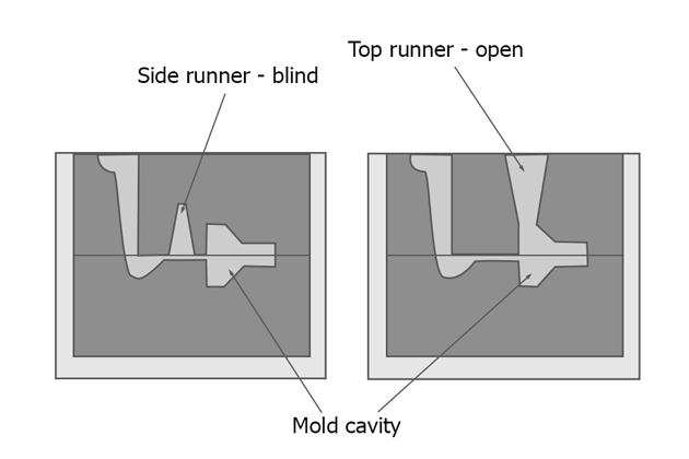
- Top gate: the gate is in the cope mold part.
The disadvantages of top gate are high metal flow turbulence, poor casting surface.
- Bottom gate: the gate is in the drag mold part. In the bottom gate, liquid metal fills the lower part of the mold cavity and gradually increases into the mold wall.
The bottom gate has the advantage of less chaos and sand erosion than the top gate.
The downside of the bottom gate is that the metal flow can be clogged due to solidification before the mold is full. The temperature range generated by the bottom gate is difficult to reach the standard causing uneven solidification.
- Parting line side gate: is the gate located along the parting line. The compartment below the parting line is filled with liquid metal through top gating, while the compartment above the parting line is filled with the bottom gating. This gate type solves the disadvantages of the two types above.
Types of gating system
There are two types of gating systems: Pressurized Gating System and Unpressurized Gating System. Choosing the right casting system with the correct area ratio will define the quality of the casting.
1. Pressurized Gating System
The Pressurized gating system is a gating system whose cross-sectional surface area decreases gradually towards the mold cavity (smaller than the narrowest downsprue-runner area). The in-gate area is minimized to put pressure on the system. At the gates, the flow rate of liquid metal is almost equal.
Sprue is always full of metal creating back pressure, which reduces air aspiration.
Here metal that is always running at high speeds becomes more chaotic and it is easy to create eddy currents in gates leading to erosion.
This system gives special priority to injection molding with cast iron materials.
2. Un-Pressurized Gating System
The Un-Pressurized Gating System is a gating system whose total surface area of the doors increases gradually towards the mold cavity (larger than the narrowest downsprue area). Liquid metal flow at gates are different.
Gating ratio
Gating ratio is the ratio between the cross-sectional area of the sprue to the total cross-sectional area of the runners to the total cross-sectional area of the ingates.
The formula for the gating ratio is As: Ar: Ag.
With the Pressurized Gating System, the gating ratio is usually 1: 2: 1 or 1: 0.75: 0.5. This system is called a “Gate control system” because ingates control the flow of the metal.
With the Unpressurized Gating System, the gating ratio is usually 1: 2: 2 or 1: 3: 3 or 1: 1: 3. This system is called a “Choke control system” because the choke controls the flow of the metal.
Table of gating ratio for various of materials:
| Materials | Gating ratio |
| Aluminum | 1:2:1 1:1.2:2 1:2:4 1:3:3 1:4:4 1:6:6 |
| Aluminum bronze | 1:2.88:4.8 |
| Brass | 1:1:1 1:2:3 1.6:1.3:1 |
| Copper | 2:8:1 3:9:1 |
| Ductile iron | 1.15:1.1:1 1.25:1.13:1 1.33:2.67:1 |
The hydraulic principle used in gating systems
Reynolds number
This is the number that helps to predict flow types with different liquid flows. The nature of the flow in the gating system can be established by calculating the Reynolds number:
Re = ρuL/µ = uL/vRe: Reynold’s number
ρ: fluid density (kg/m3)
u: velocity of flow (m/s)
L: characteristic linear dimension (m)
µ: fluid dynamic viscority (Pa.s)
v: fluid kinematics viscosity (m2/s)
- If Re> 2000, the flow is stable.
- If Re <2000, the flow is chaotic.
If the flow is turbulent, the grains of sand in the mold will be shot out of the mold and the gating system entering the mold cavity causes problems such as contamination of the casting, air aspiration in the mold, and erosion of the mold wall.
Bernoulli’s Equation
Liquid metals run through different channels in the mold according to Bernoulli’s theorem that the total head remains constant at any section.

h: potential head (m)
p: pressure (Pa)
V: molten metal velocity (m/s)
w: specific weight of liquid (N/m2)
g = 9.8 (m/s)
ρ: fluid density (kg/m3)
The gating system must be designed so that the liquid metal is always full. All cross-sections and changes in direction should avoid sharp corners and take advantage of rounded corners.
How to design gating system
To design the pouring system, the designer must adhere to the design requirements as outlined above. Here are the formulas to calculate to design a suitable gating system.
Click here for the detail.
1. Calculate pouring time
Pouring time is the time when metal fills the mold cavity. The longer the Pouring time, the higher the pouring temperature, and the filling of the mold is not guaranteed. The shorter the pouring time, the more chaotic metal flow in the mold leads to die erosion, and excessive shrinkage.
The pouring time should be optimized based on these factors:
- Casting materials
- The complexity of the casting
- Size of the casting
- Section thickness
The formula for calculating optimal pouring time:
- With Gray cast iron material with the weight less than 450kg:
t=K(1.41+T/14.59)√WK = fluidity of iron (inches) / 40
K: fluidity factor
T: average section thickness (mm)
W: mass of casting (kg)
- With Gray cast iron material with the weight greater than 450kg:
t=K(1.236+T/16.65)∛W- With steel casting:
t=(2.4335-0.3953logW)√W- With Ductile iron:
t=K₁√WK₁= 2.08 for thinner sections.
K₁= 2.67 for sections of 10 to 25mm thick.
K₁= 2.97 for heavy sections.
- With Copper alloy castings:
t=K₂∛W- Castings with thin walls and complex shapes weigh up to 450kg:
t=K₃∛W'W’: mass of the casting with gates and risers (kg)
| Thickness (mm) | |
| 1.5 – 2.5 | 1.62 |
| 2.5 – 3.5 | 1.68 |
| 3.5 – 8.0 | 1.85 |
| 8.0 – 15.0 | 2.20 |
- Casting weight ranges from 450kg – 1000kg:
t=K₄∛(W'T)| Thickness (mm) | |
| < 10 | 1.00 |
| 10 – 20 | 1.35 |
| 20 – 40 | 1.50 |
| > 40 | 1.70 |
2. Design Sprue
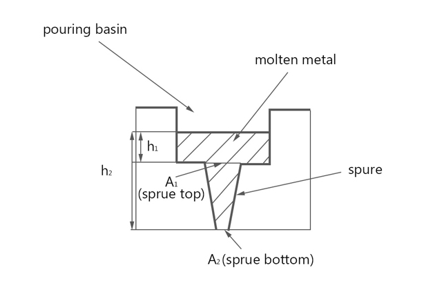
The ideal design of the sprue is that the large top ends and tapers downwards like a parabola. However, for easier production, it is recommended to use a cone cylinder. The minimum gradation level is 5%.
The sprue output circular cross-section is designed based on the area of the choke area and the gating ratio. This helps to reduce disturbances and heat loss.
The sprue calculation formula:
A₁/A₂=√h₂/√h₁h1 and h2: metal static pressure head on top sprue and bottom sprue.
A1 and A2: the respective cross-sectional area.
Design of the sprue well: A reasonable sprue well design is to make a cylinder twice the diameter of the sprue exit and twice the depth of the runner. A fillet placed between the well and the runner will help the metal to steer perpendicular smoothly.
3. Design Choke
The choke is a control area placed in the sprue well to control the flow of liquid metal flowing into the mold cavity so that the mold is filled in calculated pouring time.
The choke area plays an important role in gating systems because the area allows metal to pass through at a consistent and constant flow. The choke has the smallest ratio in the gating system compared to the other parts and cross-sectional area is smallest in the control area.
Formula to calculate choke area:
A=W/(dtC√(2gH))A: choke area (mm)
t: pouring time (s)
d: mass density of molten metal (kg/mm3)
Al: d = 2500
Cu, Fe, Ni, Co: d = 7000
C: efficiency of the used gating system (= 0.8)
W: casting weight including feeders and gating channels (kg)
g = 9.8 m/s2
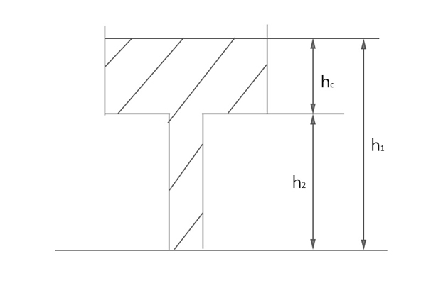
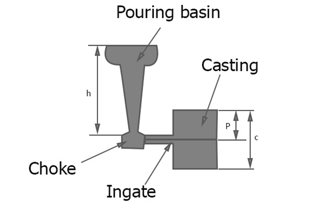
H: sprue height (mm), calculate H by:
- With top gate: H = h
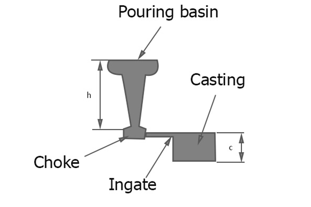
- With bottom gate: H = h – c/2
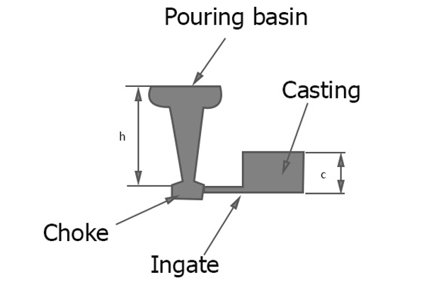
- With parting line gate: H = h – P²/2c
4. Design runner
The total cross-sectional area of the runner must be greater than the sprue exit to reduce the speed of the metal flow from the sprue to the ingates.
Priority ratio of the sprue exit to runner cross section is 1: 2. Greater proportions may result in flow separation and air aspiration.
If there are multiple ingates, the cross-sectional area of the runner after each passing through the ingate must gradually decrease by an area equal to that of the ingate to ensure a steady flow.
5. Design Ingate
Ingate must be made larger than the sprue exit to speed the metal below the limit.
- Ingate must have a smaller cross-section for easy to fettle.
- Ratio volume on cooling surface area must be less than ratio of connected part to avoid local hot spot.
- The area of the cross-sectional surface of the ingate must be proportional to the size of the connected casting area. The larger the casting area, the greater the flow required resulting in a larger ingate.
6. Design Riser (or feeder, header)
The Riser is a molten metal cavity in a mold, ready to supply metal to the mold cavity to compensate for shrinkage as the metal cools. It is placed in the final solidification position of the casting, and it is in the liquid state for the longest time. The Riser is also where the gases generated inside the mold are released during the casting process.
Optimal riser design:
- Riser size: The ratio of volume / surface area of the riser must be larger than that of the casting to maintain a liquid state. If this condition cannot be met, the metal shall be kept liquid by heating externally or by using an exothermic material in the riser.
- Position of the riser: the distance of the risers must be properly calculated based on the metal feeding distance of the risers.
- Riser shape: the recommended shape for the riser is cylindrical because globular is supposed to be the best but is difficult to cast. The bottom of the riser should be hemispherical to increase the volume / surface area ratio.
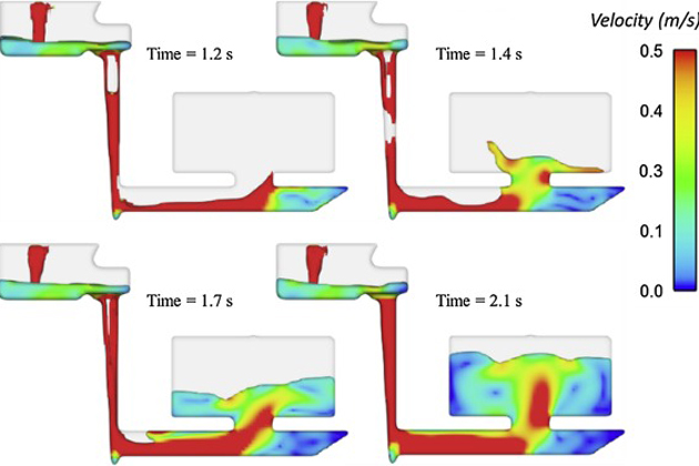
How to check the effectiveness of gating design?
The design of the gating system is tested through the following techniques:
- Water in transparent mold: the filling of the mold is recorded by the high speed X-ray camera and defect can be observed.
- High speed radiography: the filling of the mold is recorded by the high speed X-ray camera and defect can be observed.
- Open mold: part of the cope mold on the mold cavity is cut and the liquid metal flow that fills the mold cavity is rotated back by the camera.
- Contact wire sensor: the wires are placed in different parts of the mold, when the metal line touches the wire will be recorded with miltichannel recorder.
- Water in transparent mold: The addition of oil droplets or color makers will make it easier to record the speeds in different areas.
VIC is one of the leading casting aluminum and cast iron foundry manufacturers. We are focusing on manufacturing kettlebells with high high quality. If you have any questions or need metal casting foundry cooperation, do not hesitate to contact us by email: [email protected]
Read more:
How to caculate aluminum casting shrinkage
How to improve aluminum surface finish
How kettlebells are made by sand casting?
References:
- Casting & Welding Engineering by Dr.Ahmed Salad Abou Taleb
- https://en.wikipedia.org/wiki/Reynolds_number
- https://en.wikipedia.org/wiki/Bernoulli%27s_principle
- http://www.ijrerd.com/
Many thanks Mr. Dinh Tien Vu for this rich technical article
If your have more technical article for publication it will be appreciated
Very used full,
Sir , We at in INDIA (KOLHAPUR , MAHARASTAR) having one WA / Telegram Group for foundrymen and are also conducting various seminars , webinars and also having our own youtube channel for the knowledge sharing to foundry industry all over world. I would like to invite you for the few small video on the gatting design with you on cisco webex platform. we can do these videos recording as per pour convenience and then load it on you tube. Pl send me if you are interested to do it. with us.
Our YouTube channel “Dynamic Foundry Group”
thanks for this document.
Nevertherless there is a mitake in the Reynolds condition.
The flow is turbulent for Re>2000 not for Re <2000